We are innovators combining science and technology with deep industry expertise to solve complex subsurface and surface challenges. Learn more about the technology behind our solutions.
CMG has a rich history of bringing industry-first solutions to the market. Our expertise encompasses a broad spectrum of energy workflows and our technology can help energy companies navigate this complex landscape.
We are a global software and consulting company that combines science and technology with deep industry expertise to solve complex subsurface and surface challenges for the new energy industry around the world.
Coupled Simulation of Underground Coal Gasification (UCG) Using CMG STARS
Underground Coal Gasification transforms coal into energy underground, but doing so safely and efficiently requires understanding one of the most complex coupled subsurface processes in energy engineering.
It is an in-situ process that converts coal into syngas by injecting oxidants into a coal seam and producing combustible gases through a network of high-temperature chemical reactions.
In this study, CMG STARS was used to develop a fully coupled thermal-hydro-mechanical-chemical (THMC) model of UCG, capturing the evolution of the gasification cavity, chemical reactions, composition of produced syngas, production behavior, and subsidence.
Outcome: The model demonstrates how coupled simulation can predict cavity growth, gas production, and geomechanical deformation, providing critical insights for safe and efficient UCG operations.
What is Underground Coal Gasification (UCG)?
UCG is a process where coal is converted into gas underground, rather than being mined and processed at the surface.
The process involves:
Injecting oxidants (air, oxygen, steam) into a coal seam
Initiating combustion and gasification reactions
Producing syngas (CO, H₂, CH₄, CO₂) through a production well
How It Differs from Conventional Reservoir Processes?
Unlike oil & gas production:
Solid coal is converted into gas in-situ
A cavity is created and grows over time
Rock structure and stress conditions evolve dynamically
This makes UCG not just a flow problem, but a reactive, deforming system.
Why UCG is Complex to Model?
UCG is one of the most complex subsurface processes to simulate because it requires simultaneous coupling of multiple physical domains.
1. Chemical Reactions and Kinetics
UCG involves multiple reactions, including:
combustion
steam gasification
methanation
pyrolysis
Example (Pyrolysis: from the model below):
Coal 🡪 Char + CO + CO₂ + H₂ + CH₄
Despite the interdependencies among the reactions, each reaction has:
different activation energies
temperature dependencies
competing pathways
2. Extreme Thermal Conditions
Temperatures can exceed 1000°C locally
Strong heat gradients develop
Heat drives reaction rates
3. Complex Fluid Transport
Gas flows through evolving porous media with dynamically changing structure
Permeability and porosity vary significantly over time
Composition changes continuously, particularly during the early stages of the cavity formation
Multiphase flow may occur if tar is formed, although this is rare and generally not significant
4. Evolving Geometry (Cavity Growth)
Coal consumption significantly increases pore volume and, consequently, porosity over time. This alters gas-phase flow behavior, transitioning it from Darcy flow to non-Darcy and potentially turbulent flow.
Collapse of coal and char from the roof and sidewalls of the cavity changes flow paths and gas mixing within the cavity, which can indirectly affect reaction efficiency.
This implies that the treatment of coal seams in the UCG process is fundamentally different from that of conventional oil and gas reservoirs, where the available pore volume for fluids changes far less significantly.
5. Coupled Geomechanics
As the cavity grows:
overburden stress redistributes
subsidence occurs
fracture patterns may change
This directly impacts:
permeability and porosity
flow pathways
operational safety
Solution: CMG STARS Offers a Fully Coupled Approach
CMG STARS enables:
thermal simulation (high-temperature processes)
chemical reactions and kinetics
solid-solid (coal 🡪 char) and solid-gas (char 🡪 gas) conversion
multiphase flow
dynamic porosity/permeability evolution
coupled geomechanics (subsidence, stress)
This makes it uniquely suited for UCG modeling.
Operational Context: Model Overview
From the simulation setup:
Grid: 50 × 50 × 12
Block size: 0.5 m × 0.5 m × 0.5 m
Wells: 1 injector and 1 producer
Perforations: Layer 10
Initial porosity: ~8%
Initial Conditions
Temperature: ~60°C
Pressure: ~11.5 MPa
Water saturation: ~0.70
Coal concentration: ~12,700 gmol/m³
Reactions Modeled
The simulation includes:
pyrolysis
combustion
gasification reactions
With full kinetic parameters:
activation energy
frequency factors
This enables realistic gas composition prediction. The key step in modeling UCG reactions in STARS is representing the pyrolysis process as accurately as possible, in which coal is consumed to produce char that subsequently combusts and generates the required in-situ heat. In addition, this process produces significant quantities of gaseous species that serve as reactants in subsequent gasification and combustion reactions. Leveraging coal elemental analysis to derive realistic stoichiometric coefficients for the pyrolysis reaction is therefore of critical importance.
Key Results
1. Gas Production Behavior
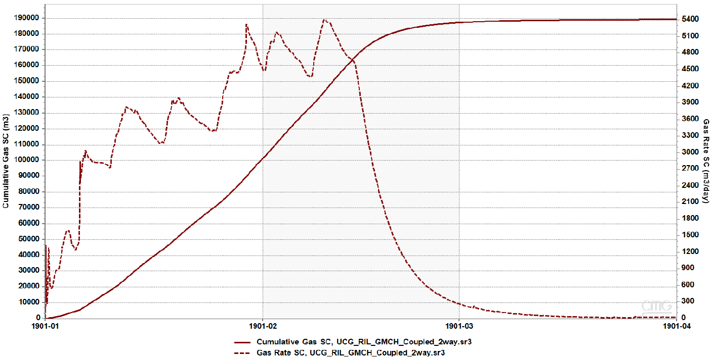
The simulation shows:
rapid increase in gas production
stabilization as cavity develops
eventual decline as coal is consumed
Figure 1: Simulated gas production showing rapid initial increase as gasification reactions intensify, followed by stabilization and eventual decline as coal is consumed and the cavity evolves.
Insight
Gas production is directly linked to:
reaction front movement
available coal volume
evolving flow pathways connecting the injection points (cavities) to production perforation
Gas production strategies must account for reaction front progression and cavity evolution to avoid premature decline.
2. Cavity Growth and Porosity Evolution
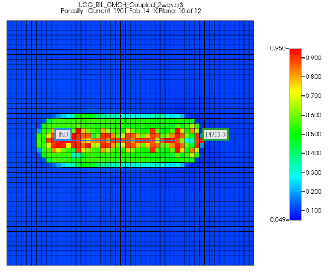
After ~90 days:
significant increase in porosity near injection zone
formation of a clear gasification cavity
Figure 2: Shows the formation and expansion of the gasification cavity between injector and producer wells. Increased porosity highlights regions where coal has been consumed and converted into gas.
Insight
The cavity is not uniform. It evolves based on:
heat distribution
reaction kinetics
flow direction, for example, rapidly developing upward as gas components rise within the cavity
Gas component residence time, which is influenced by the production rate and the degree of cavity-producer connectivity
3. Temperature Front Propagation
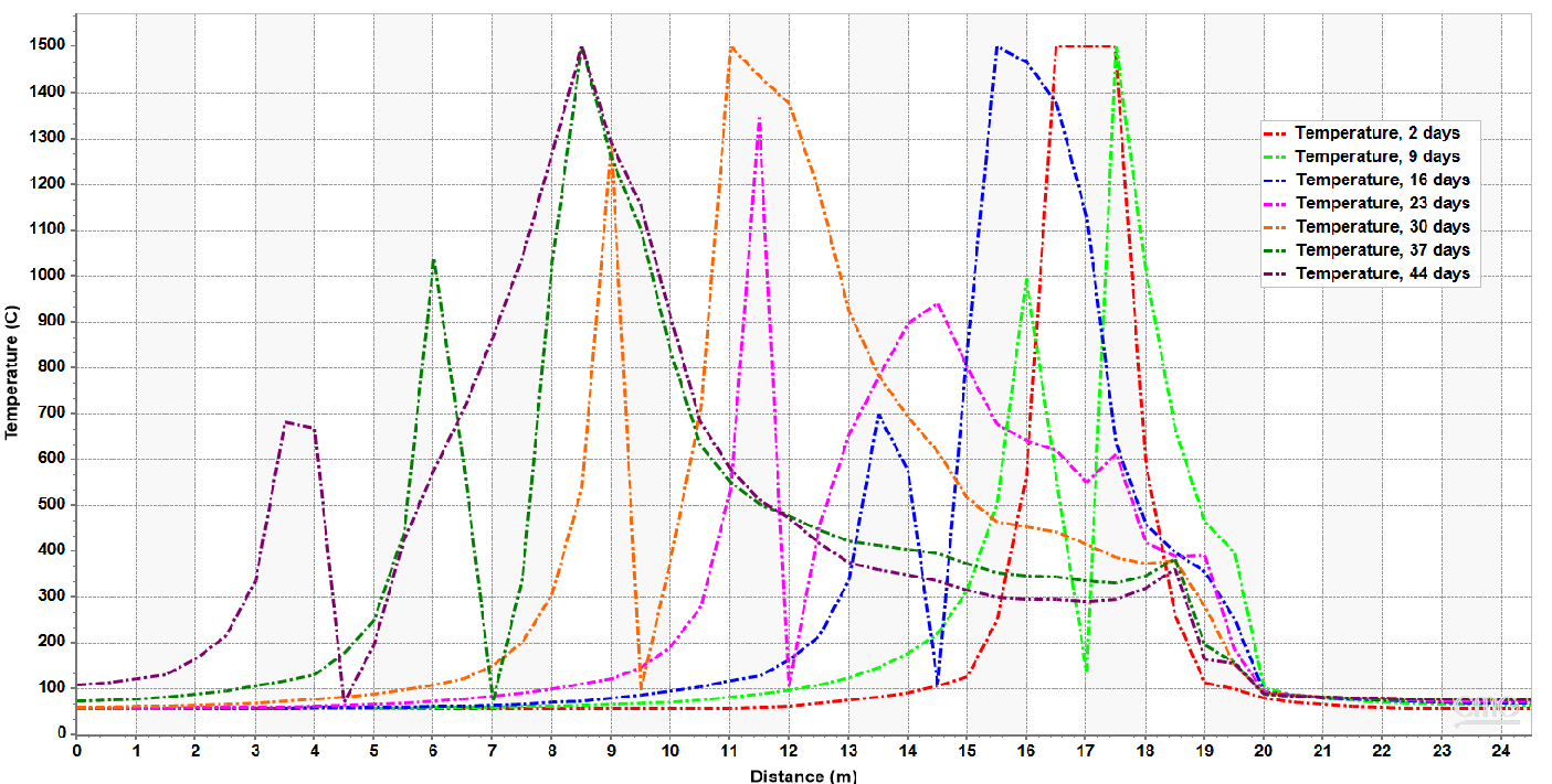
Pyrolysis and char combustion reactions occur mainly along the cavity boundaries. However, due to the tendency of gas flow toward the production perforation, the high-temperature front is typically oriented in that direction and gradually advances toward the producer over time.
Figure 3: Shows temperature profiles at different times showing the advancement of the high-temperature reaction zone. Thermal gradients define the active gasification region and control reaction kinetics and gas generation.
Insight
High-temperature zones define exothermic reaction regions
Heat transfer, mainly due to gas convection flow, controls reaction progression
Thermal breakthrough, characterized by high temperatures at the production perforations, dictates production behavior
4. Coal-to-Char Conversion
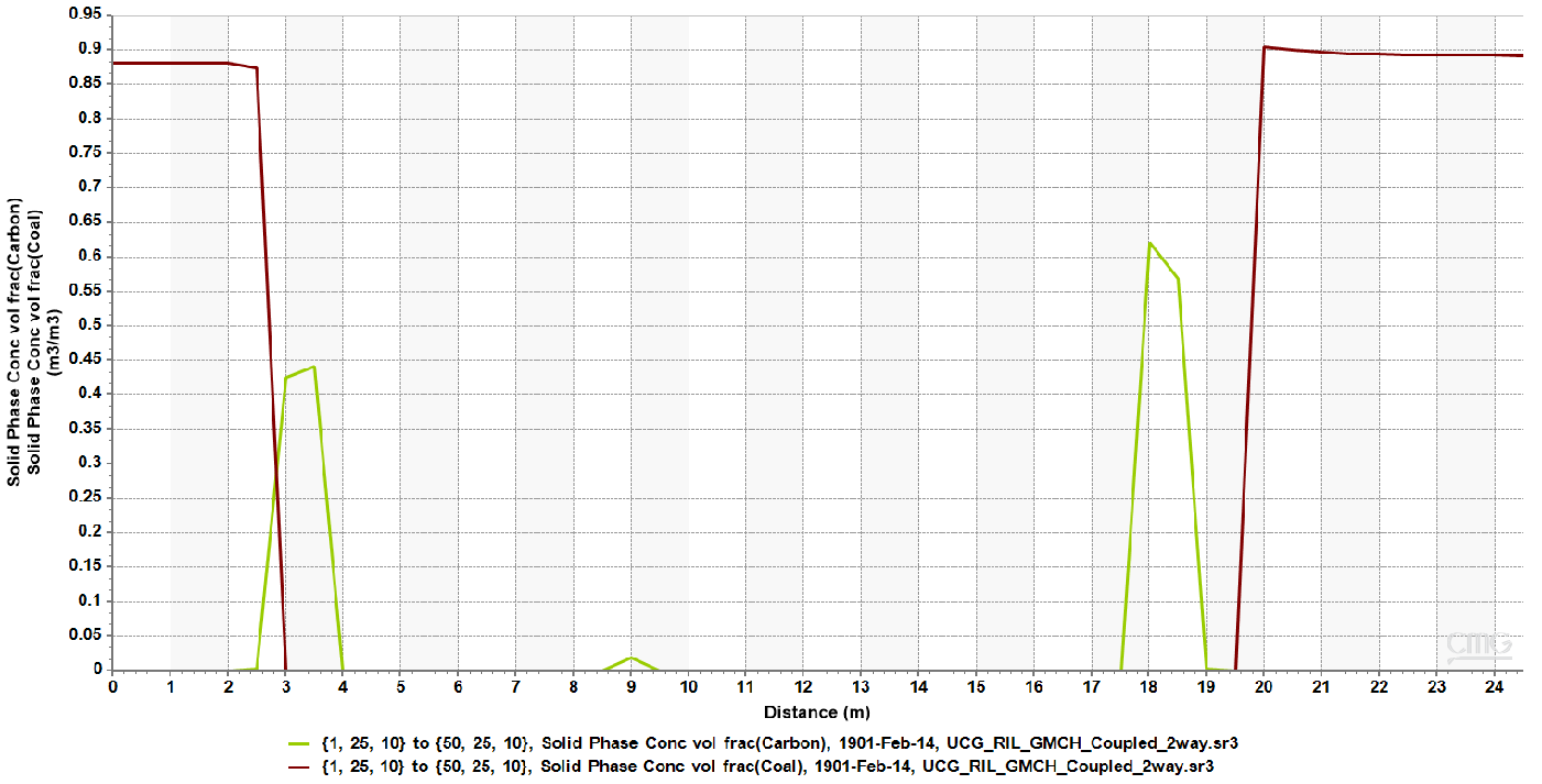
Results show:
conversion of coal near injection zone at early time and at the cavity boundary at later time
formation of char due to pyrolysis process
progression toward producer
Figure 4: Distribution of coal and char at the end of injection, showing progressive consumption of coal near the injector and transformation into char as reactions advance toward the producer.
Insight
Reaction zones migrate dynamically, altering:
material composition
flow properties
gas yield
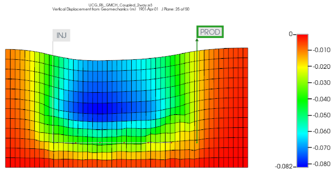
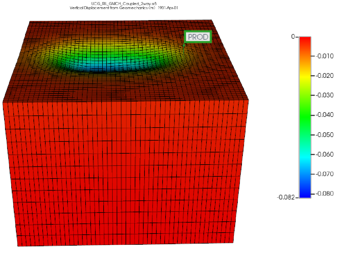
5. Geomechanical Response and Subsidence
Simulation shows:
measurable subsidence after 90 days
stress redistribution across reservoir
Figure 5: 3D visualization of subsidence resulting from coal removal and cavity expansion, highlighting the spatial extent of geomechanical deformation.\
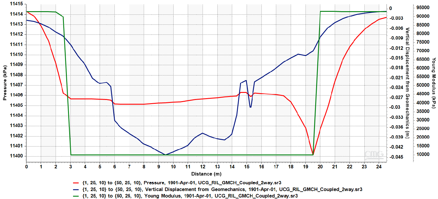
Figure 6: Integrated view of pressure distribution and vertical displacement, demonstrating the interaction between fluid flow, reaction progression, and geomechanical deformation.
Insight
Geomechanics directly affects:
structural integrity
flow pathways
operational safety
Subsidence prediction is critical for ensuring well integrity and minimizing surface impact.
Why This Matters
This case demonstrates that UCG is not just about maximizing gas production.
It requires understanding:
where the cavity will grow
how reactions evolve spatially
how the reservoir deforms
how production changes over time
Key Takeaways
UCG is a fully coupled thermal-hydro-mechanical-chemical (THMC) process
Cavity growth (resulting from reactions) and subsidence (resulting from material deformation) must be modeled together
Gas production depends on type and rate of injected oxidants, reaction kinetics, and heat distribution
Flow behavior evolves as coal is consumed
CMG STARS enables end-to-end modeling of all governing physics
Best Practices for UCG Modeling
Include reaction kinetics, not just simplified conversions
Model cavity growth dynamically
Incorporate geomechanical effects for safety and accuracy
Perform time-dependent simulations to capture system evolution
Conclusion
Underground Coal Gasification is one of the most complex subsurface processes to model, requiring the integration of chemical reactions, fluid flow, heat transfer, and geomechanics.
This study demonstrates that CMG STARS provides a unified framework to simulate these coupled processes, enabling accurate prediction of gas production, cavity evolution, and subsurface deformation.
By capturing the full system behavior, engineers can move beyond simplified assumptions and make more informed decisions about UCG design, operation, and safety.