We are innovators combining science and technology with deep industry expertise to solve complex subsurface and surface challenges. Learn more about the technology behind our solutions.
CMG has a rich history of bringing industry-first solutions to the market. Our expertise encompasses a broad spectrum of energy workflows and our technology can help energy companies navigate this complex landscape.
We are a global software and consulting company that combines science and technology with deep industry expertise to solve complex subsurface and surface challenges for the new energy industry around the world.
Improving Oil Recovery in the Mature La Cira Infantas Oilfield using iSegwell Advanced Wellbore Modelling & CMOST Optimization Tools
Reservoirs with heterogeneous flow units that have considerable differences in flow capacity usually encounter low recovery factors during waterflooding, due to low sweep efficiency and early water breakthrough in high permeability flow units. Inflow Control Devices (ICD) are commonly used to control the volume of water injection (WI) depending on the properties of each flow unit and the waterflooding (WF) pattern configuration with the objective of improved sweep efficiency.
Challenges
Optimization of ICD configurations in the injector well involves simultaneous adjustment of multiple parameters in order to provide the optimal WI profile which improves sweep efficiency and maximizes oil production for the WFpattern. These parameters include the number of packers and side pocket mandrels, the diameters of the selective valves, the water injection rate, and the bottom hole injection pressure. In this case study CMOST was used to improve two objective functions which maximize the cumulative oil production and minimize cumulative water production from an inverted 5-spot WF pattern over 15 years.
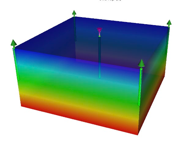
Figure 1: An example of the inverted 5-spot water flood pattern
Reservoir Study
This workflow includes a 3D reservoir model of 5-spot WFpattern (Figure 1) using average reservoir properties. The model was calibrated using the historical pressure and production data from analog wells in the same area of the La Cira Infanta Field (LCI) located in Colombia, where the new waterflood pattern is planned (Figure 2). This model was fully coupled with an advanced multi-segmented wellbore model (iSegWell) to represent the selective injection string with multiple packers and side pocket mandrels and valves. The injector well was selected as a candidate to evaluate different well configurations using flow control devices, in order to optimize the sweep efficiency and increase the recovery factor of the pattern.
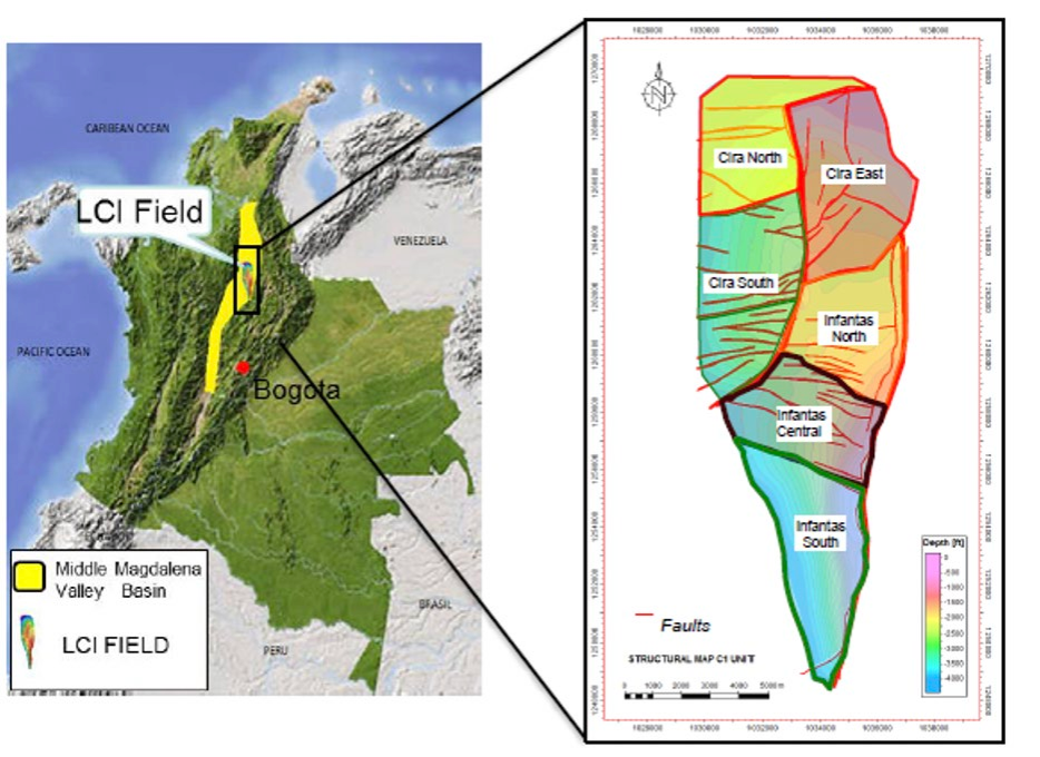
Figure 2: LCI oilfield location map in Colombia and field layout with fault blocks
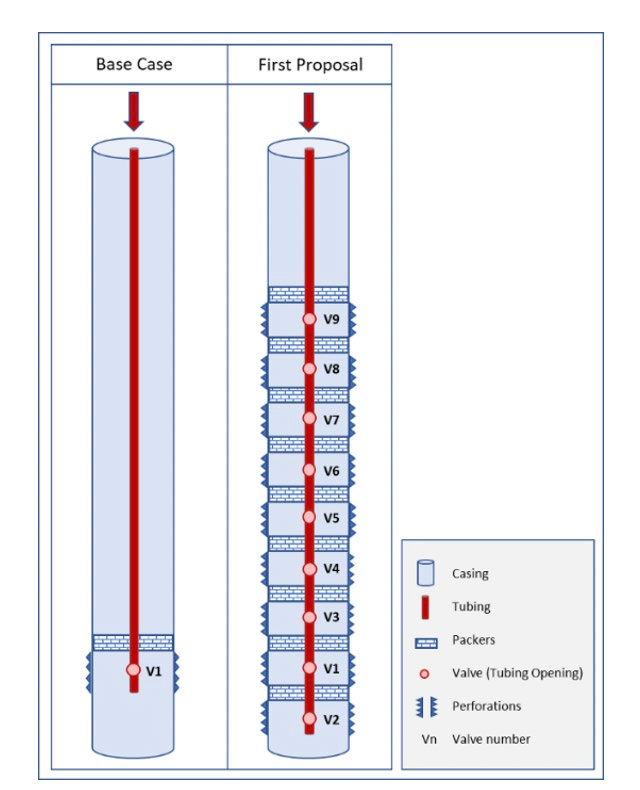
Figure 3 shows a schematic of the selective injection model for a water injector well. This particular water injector was initially perforated in the reservoir’s bottom two sand layers and had injected water for several years.
This initial completion design was defined as the base case. For the optimization stage, the first proposal of the injector well was a single tubing completion with nine flow control devices. The injector well was represented in the reservoir simulator using an iSegWell wellbore model which uses multi-segmented well theory for accurately modelling the flow and pressure gradient between the wellhead and perforations while including realistic tubing configurations such as packers and mandrels and valves.
Figure 3: Water injector modeling with packers and mandrels/valves (not to scale)
Solution
CMOST was used in conjunction with IMEX to optimize the water injection strategy where two objective functions were defined to both maximize the cumulative oil production and to minimize cumulative water production from an inverted 5-spot WF pattern over 15 years. The Pareto Particle Swarm method was used to determine the optimal completion and operating strategy.
Based on the well completions proposal, the parameters to be evaluated were:
Number of valves [1 to 9 valves]
Valve opening position as a fraction [0 to 1.0, where 0 is closed and 1.0 is fully open]
Water injection rate [250 to 1000 bwpd]
Bottom hole injection pressure [1000 to 3200 psi]
Key Results
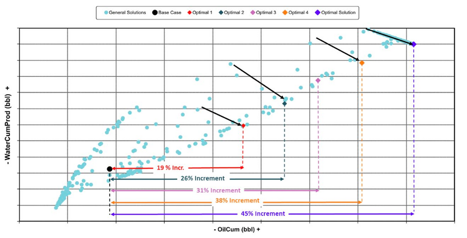
After 500 runs, the best 5 cases were selected and rated from Optimal 1 to Optimal Solution. Figure 4 shows the Pareto Front cross plot (Water Cumulative Produced vs. Oil Cumulative), where it can be seen the progress and improvement of results using the optimization methodology can be seen. Where black arrows were placed, shows how the optimizer tried to decrease the accumulated water produced as the oil produced increased.
Figure 4: Pareto Front cross plot of cumulative oil versus cumulative water produced
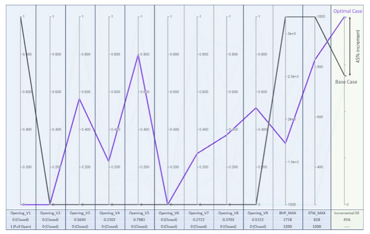
Figure 5 shows the parallel coordinates plot, a tool that simultaneously compares multiple input parameters that were evaluated during the optimization. The black line represents the base case while the purple line represents the optimal case which obtained 45% greater oil production than the base case by optimizing the number of valves and the opening fraction of each valve (or ICV). In this particular 5-spot WF pattern, it is noted that the valves numbered 1, 2, and 6 are fully closed and the remaining six valves are partially opened with different percentages. This combination of input parameters provides the maximum oil production and minimum water production possible. In other words, three valves were not required to achieve the optimal well-completion proposal. This not only maximizes the oil production but also saves well completion costs by excluding three out of nine mandrels/valves in this case.
Figure 5: Parellel Coordinates Plot
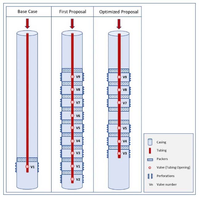
Figure 6 shows the comparison of the Base Case completion proposal with nine valves against the optimized completion proposal with six valves that was obtained from the multi-phase flow simulation and optimization workflow.
Figure 6: Well-completion schematics between Base, First, and Optimized proposals (not to scale)
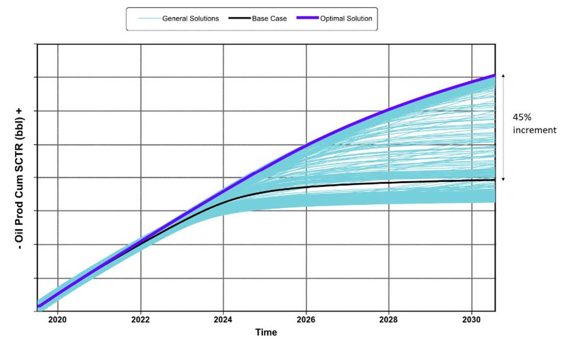
For a case study of the inverted 5-spot WF pattern, Figure 7 presents the cumulative oil production curves from all simulation runs. Highlighted cases are the base case in black and the optimal case in purple. Note that the optimal case delivers 45% incremental oil above the base case. Another important result to note is the cumulative water injection.
Figure 7: All simulation runs: Optimal (Purple) case delivers 45% incremental oil above Base case
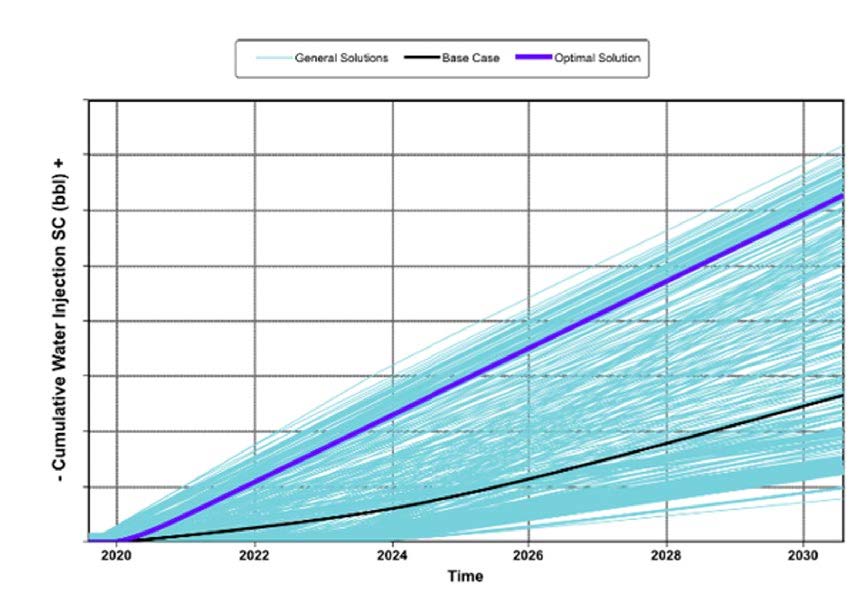
Figure 8 shows that the optimal case (purple curve) requires more than twice the water injection, volume of the base case (black curve) in order to increase oil production by 45%. The average WI rates are 830 bwpd and 400 bwpd for the optimal case and the base case, respectively.
Figure 8: All simulation runs: Optimal (blue) case requires more than 2 times the water injection of the Base case
Benefits
Improve Sweep efficiency in a multi layered reservoir affected by variations in zonal pressures.
Reduce completion costs by selecting the appropriate configuration for inflow control devices prior to implementation.
Reduce engineering time to design a waterflooding project, maximizing oil production and minimizing water production.
45% increase in incremental oil compared to base case. Reduced completion costs by about 30%. Optimal case required only six selective valves, instead of the proposed nine.